Most of machine manufacturers have determined period and scope of predictive maintenances for manufactured machines to ensure maximum reliability and performance for the end users. Scope of those activities based on stress factors (Electrical, mechanical, thermal and environmental) Meanwhile period of maintenances depend on running hours and number of start (roughly each start equals to 20 hours running effect)
In order to clarify each predictive maintenance issue there are four categorised maintenance activities.
These are L1, L2, L3 and L4.
L1 Maintenance:
Period is every 6-12 month and must be executed by an expert. Total duration of this activity is 3-5 hours and during the study machine has to be in running position. No need to stop the machine.
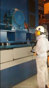
- A visual check is done with taken snaps and related notes (oil leakages, environmental conditions,..etc) are mentioned in the check list.
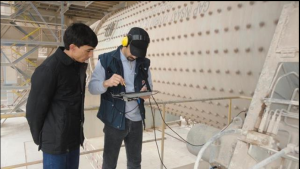
- A vibration test is carried out from both NDE and DE sides
- Time waveform analysis
- Frequency spectrum analysis
- Phase measurements (especially for crack doubts)
- Critical speed and resonance issues
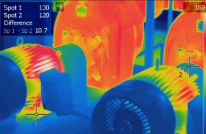
- Thermal camera records for detection of general surface temperature and probable hot spot due to any mechanical or electrical effect. These thermo graphs are used as references for next records.
L2 Maintenance:
Period is every 1-2 years, it takes around 8-10hours by an expert for one motor or generator. At the beginning L1 is carried out then machine is stopped for 3-5 hours.
- L1 is carried out during machine is running
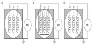
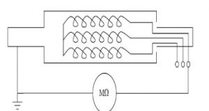
- IR tests are executed for stator, rotor and excitation windings according to IEEE43-2000 standard.
- PI and DAR values are recorded and mentioned in the report
- Diodes checks by a multimeter and varistor visual check
- RTDs and heater electrical checks
- CTs and PTs visual checks
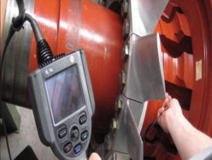
- A visual inspection through inspection window or any suitable space in order to find out below items;
- Contamination (oil, dust, coal and any other debris)
- Overhangs supports, crimped joints, fixing plates between end windings, slot wedges
- PD marks
- Discoloration due to high temperature
- Rotor surface and discoloration check
L3 Maintenance:
Period is 3-5 years according to running hours and number of start (1 start has 20 hours aging effect) It takes around 2 days by one mechanical and one electrical experts. First L1 and L2 are carried out then continue with sleeve bearing inspection scope
- L1 and L2 are carried out
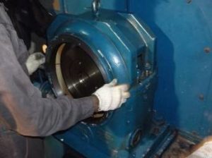
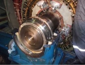
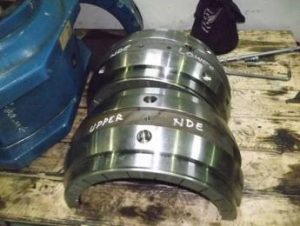
- Dismantling of DE and NDE sides bearings
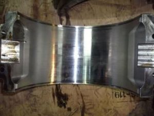
- Inspection of bearing shells both for surface condition and clearance according to shaft diameter
- Oil ring, fix and labyrinth seal checks
- Oil sample for oil inspection (PPM checks)
- Changing of lubrication oil if necessary
- Assembly of DE and NDE sides bearings
- Start up of machine and execution of L1
L4 Maintenance:
Period is 8-10 years according to running hours and number of starts. Minimum one mechanical and one electrical and 4 co workers are required for L4 scope. It takes around 8-12 days according to size of machine and site conditions. First L1,L2 and L3 are executed then continue with L4 scope of work.
- Execution of L1, L2 and L3
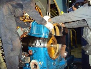
- Disassembly of coupling
- Dismantling of heat exchanger
- Dismantling of end covers and air guide block
- Exciter stator dismantling (Salient pole type generators)
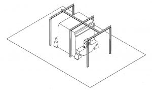
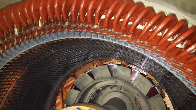
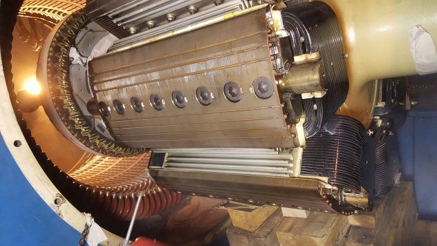
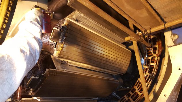
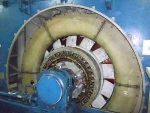
- Rotor sliding out through cranes and chan blocks
- Installation of rotor extension part
- Completion of rotor withdrawn until having nough space for cleaning, local repair and inscpetion
- Fixing rotor for maintenance position
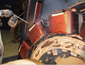
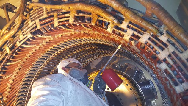
- Cleaning stator, rotor and excitation windings by CO2 or solvent through pressurized dry air
- PD mark inspection and marks on stator windings
- Stator slot wedge visual and mechanical checks
- Scrubbing old varnish on stator core
- Applying conductive varnish
- Installation of new wedges instead of loose or missing ones
- Applying semi-conductive varnish to end windings
- Applying of protective varnish
- Electrical tests before and after cleaning and varnishing
- Assembly of machine
- Start up of machine
- Execution of L1 as final stage of maintenance
A draft drawing of simple structure used for rotor sliding purpose during L4 maintenance
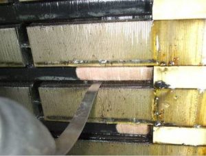
Contamination is a result of missing maintenance and improper environmental conditions
Contamination causes more PD and as a consequence speeds up deterioration
Contamination mostly happens due to stack dust, coal on oil coming since leakage on bearings
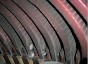
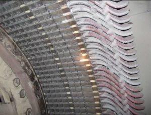
PD Marks are mostly white powders on overhangs
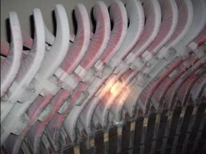
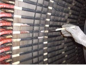
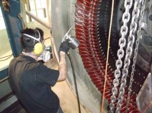
Cleaning of windings
One of the most effective achievements during L4 is cleaning of most stressful area that is overhangs
After a successful cleaning overhangs get ready for protective final coating vanish
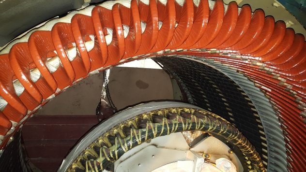
Inspections after cleaning
Deterioration on conductive tapes become more visible after cleaning
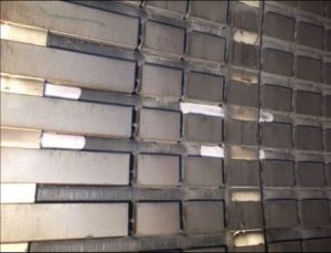
Gap between slot and coil is checked on damaged area to realise degree of deterioration
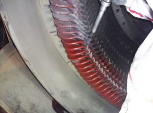
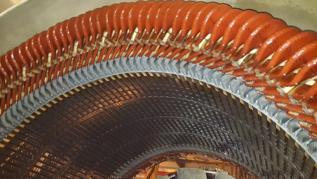
Local repairs after cleaning
Damaged conductive tapes are repaired by applying conductive varnish
In order to create an overlap between overhang stress grading and slot corona a semi conductive varnish is applied to end windings by keeping overhang with applied conductive varnish
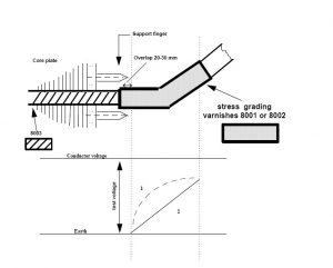
Applying of conductive varnish tos lot area
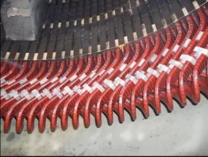
Final protective varnish application
Salient pole rotor varnish application
Final protective varnish for end winding area
Assembly of machine
Execution of L1 after completion of L4